Measurements and Experimentation Exe-1B Measurement of Length Long Answer Type Questions for ICSE Class-9 Concise Physics Selina Publishers Solutions of Chapter-1. There is the solutions of short Answer type Questions of your latest textbook which is applicable in 2023-24 academic session. Visit official Website CISCE for detail information about ICSE Board Class-9
Measurements and Experimentation Exe-1B Measurement of Length
Long Answer Type for ICSE Class-9 Physics Selina Concise Solutions
| Board | ICSE |
| Class | 9 |
| Subject | Physics |
| Writer / Publication | Concise selina Publishers |
| Chapter-1 | Measurements and Experimentation |
| Exe – 1 B | Measurement of Length |
| Topics | Solution of Exe-1(B) Long Answer Type |
| Academic Session | 2023-2024 |
Measurement of Length Exe-1(B) Long Answer Type
Measurements and Experimentation ICSE Class-9 Concise Physics Selina Solutions
Page 22
Question 1. What is meant by zero error of vernier callipers ? How is it determined? Draw neat diagrams to explain it. How is it considered to get the correct measurement?
Answer : Due to mechanical errors, sometimes the zero mark of the vernier scale does not coincide with the zero mark of the main scale, the vernier callipers is said to have zero error.
It is determined by measuring the distance between the zero mark of the main scale and the zero mark of the vernier scale. The zero error is of two kinds
Positive zero error
(i) Positive zero error: On bringing the two jaws together, if the zero mark of the vernier scale is on the right of the zero mark of the main scale, the error is said to be positive.
To find this error, we note the division of the vernier scale, which coincides with any division of the main scale. The number of this vernier division when multiplied by the least count of the vernier callipers, gives the zero error.
For example, for the scales shown, the least count is 0.01 cm and the 6th division of the vernier scale coincides with a main scale division.
Zero error = +6 × L.C. = +6 × 0.01 cm
= +0.06 cm
Negative zero error
(ii) Negative zero error: On bringing the two jaws together, if the zero mark of the vernier scale is on the left of the zero mark of the main scale, then the error is said to be negative.
To find this error, we note the division of the vernier scale coinciding with any division of the main scale. The number of this vernier division is subtracted from the total number of divisions on the vernier scale and then the difference is multiplied by the least count.
For example, for the scales shown, the least count is 0.01 cm and the sixth division of the vernier scale coincides with a certain division of the main scale. The total number of divisions on vernier callipers is 10.
Zero error = – (10 – 6) × L.C.
= – 4 × 0.01 cm = – 0.04 cm
Correction:
To get correct measurement with vernier callipers having a zero error, the zero error with its proper sign is always subtracted from the observed reading.
Correct reading = Observed reading – zero error (with sign)
Question 2. Draw a neat and labelled diagram of a vernier callipers. Name its main parts and state their functions
Answer : Diagram of vernier callipers:
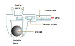
Main parts and their functions of a vernier callipers :
Main scale: It is used to measure length correct up to 1 mm.
Vernier scale: It helps to measure length correct up to 0.1 mm.
Outside jaws: It helps to measure length of a rod, diameter of a sphere, external diameter of a hollow cylinder.
Inside jaws: It helps to measure the internal diameter of a hollow cylinder or pipe.
Strip: It helps to measure the depth of a beaker or a bottle.
Question 3. Describe in steps, how would you use a vernier callipers to measure the length of a small rod ?
Answer : Measuring the length of a small rod using vernier calipers:
The rod whose length is to be measured is placed in between the fixed end and the vernier scale as shown in the figure.
In this position, the zero mark of the vernier scale is ahead of 1.2 cm mark on main scale. Thus the actual length of the rod is 1.2 cm plus the length ab (i.e., the length between the 1.2 cm mark on the main scale and 0 mark on vernier scale).
To measure the length ab, we note the pth division of the vernier scale, which coincides with any division of main scale.
Now, ab + length of p divisions on vernier scale = length of p divisions on main scale
Alternatively, ab = length of p divisions on the main scale – length of p divisions on the vernier scale.
= p (length of 1 division on main scale – length of 1 division on vernier scale)
= p × L.C.
Therefore, total reading = main scale reading + vernier scale reading
= 1.2 cm + (p × L.C.)
Question 4. Draw a neat and labelled diagram of a screw gauge. Name its main parts and state their functions.
Answer : Diagram of screw gauge:

Main parts and their functions of a screw gauge :
- Ratchet: It advances the screw by turning it until the object is gently held between the stud and spindle of screw.
- Sleeve: It marks the main scale and base line.
- Thimble:It marks the circular scale.
- Main scale: It helps to read the length correct up to 1 mm.
- Circular scale: It helps to read length correct up to 0.01 mm.
Question 5. Describe the procedure to measure the diameter of a wire with the help of a screw gauge.
Answer : The wire whose thickness is to be determined is placed between the anvil and spindle end, the thimble is rotated until the wire is firmly held between the anvil and spindle. The rachet is provided to avoid excessive pressure on the wire. It prevents the spindle from further movement. The thickness of the wire could be determined from the reading as shown in the figure below.
The pitch of the screw = 1 mm
L.C. of screw gauge = 0.01 mm
Main scale reading = 2.5 mm
46th division of circular scale coincides with the base line.
Therefore, circular scale reading = 46 × 0.01 = 0.46 mm
Total reading = Main scale reading + circular scale reading
= (2.5 + 0.46) mm
= 2.96 mm
In order to measure the diameter of a wire with the help of a screw gauge we follow the following steps —
1. Find the least count and the zero error of the screw gauge.
2. Turn the ratchet anticlockwise, so as to obtain a gap between the stud A and the flat end B. Place the wire in the gap between the stud A and the flat end B. Then turn the ratchet clockwise so as to hold the given wire gently between the stud A and the flat end B of the screw.
3. Note the main scale reading.
4. Note that division p of the circular scale that coincides with the base line of the main scale. This circular scale division p when multiplied by the least count, gives the circular scale reading i.e., Circular scale reading = p x L.C.
5. Add the circular scale reading to the main scale reading to obtain the total reading (i.e., the observed diameter of the wire).
6. Repeat it by keeping the wire in perpendicular direction. Take two more observations at different places of the wire and record them in a table.
— : End of Measurements and Experimentation Exe-1B Measurement of Length Long Answer Type Questions Selina Solutions :–
Return to Concise Selina Physics ICSE Class-9 Solutions
Thanks
Please share with your friends