V L C R Circuit Numerical Class-12 Nootan ISC Physics Solution Ch-12 Alternating Current Step by step solutions of Kumar and Mittal Physics of Nageen Prakashan as council latest prescribe guideline for upcoming exam. Visit official Website CISCE for detail information about ISC Board Class-12 Physics.
V L C R Circuit Numerical Class-12 Nootan ISC Physics Solution Ch-12 Alternating Current
| Board | ISC |
| Class | 12 |
| Subject | Physics |
| Book | Nootan |
| Chapter-12 | Alternating Current |
| Topics | Numericals on V L C R Circuit |
| Academic Session | 2025-2026 |
Numericals on V L C R Circuit
Class-12 Nootan ISC Physics Solution Ch-12 Alternating Current
Que-34: In an AC circuit with all components connected in series, the emf and the current are given by V = 200 sin(314t + π/6) volt and I = 5 sin 314t ampere. Obtain (i) the peak values of emf and current, (ii) the frequency of the AC source, (iii) the phase difference between V and I (iv) impedance of the circuit (ISC 2000)
Ans- (i) peak value of emf = 200 V
peak value of current = 5 A
(ii) frequency = ω/2π = 314/2 x 3.14 = 50 Hz
(iii) phase difference = π/6
(iv) Z = Vo/io = 200/5 = 40 Ω
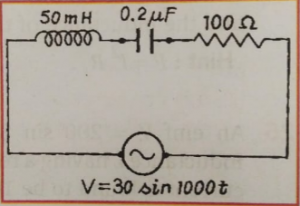
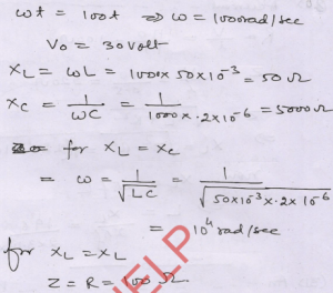
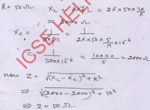
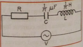
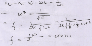
Que-35: In the given circuit, calculate the inductive reactance and the capacitive reactance. What should be the source frequency so that the two reactance become equal in magnitude? What would then be the impedance of the circuit?
Ans-
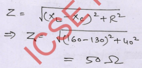
Que-36: In an L-C-R AC circuit, the reactance of L and Care 160 Ω and 130 Ω respectively and R is 40 Ω. Find the impedance of the circuit.
Ans-
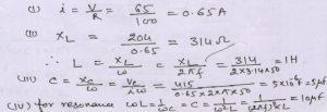
Que-37: In the given L-C-R series circuit fed by 220 V-50 Hz AC mains, find (i) current in the circuit, (ii) value of inductor L, (iii) value of capacitor C and (iv) value of C (for the same L) required to produce resonance. The voltmeter readings across R, L and C are as shown in the figure.
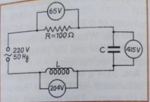
Ans-
Que-38: What will be the readings in the voltmeter and the ammeter shown in the figure?
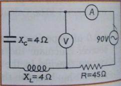
Ans-
Que-39: A resistor of 50 Ω, an inductor of (20 / π) Η and a capacitor of (5 / π) μF are connected in series to a voltage supply of 230 V-50 Hz. Find the impedance of the circuit.
Ans-
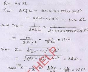
Que-40: A 40 Ω resistor, a 3 mH inductor and a 2 µF capacitor are connected in series to a 110 V-5000 Hz AC source. Find the current in the circuit.
Ans-
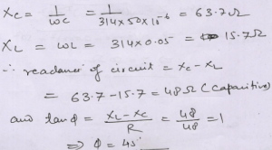
Que-41: A 50 µF capacitor, a 0.05 H inductor and a 48 Ω resistor are in series with an AC source of emf V = 310 sin 314t Calculate the reactance of the circuit and its character. What is the phase angle between the current and the applied emf?
Ans-
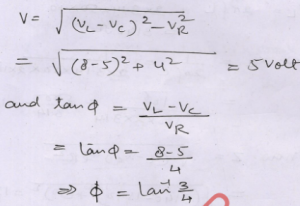
Que-42: An alternating emf V is applied across a series L-C-R circuit. The peak values of the alternating voltage developed across the three components are marked in the figure. Determine the peak value of the applied emf and the phase difference between the applied emf and the current in the circuit.
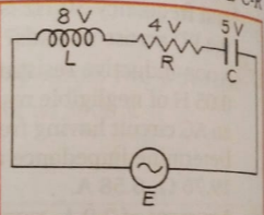
Ans-
Que-43: The main-supply voltage of the alternating-current circuit shown in the figure is constant, but its frequency f is variable. For what frequency the voltage across the resistance R will be maximum?
Ans- for XL = XC the impedance will be equal to R and applied voltage will be equal to voltage across R
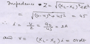
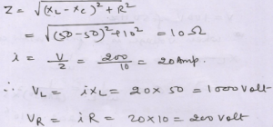
Que-44: 200 V AC is applied at the ends of an L-C-R circuit. The circuit consists of an inductive reactance XL = 50 Ω, capacitive reactance Xc = 50 Ω and resistance R = 10 Ω. Calculate the impedance of the circuit and also the potential differences across L and across R. What will be the potential difference across L-C?
Ans-
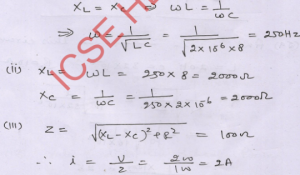
Que-45: A 2 µF capacitor, 100 Ω resistor and 8 H inductor are connected in series with an AC source. What should be the frequency of this source for which the current drawn in the circuit is maximum? If the peak value of emf of the source is 200 V, find for maximum current: (i) the inductive and capacitive reactance in the circuit, (ii) total impedance of the circuit, (iii) peak current in the circuit, (iv) phase relation between voltages across inductor and resistor, (v) phase difference between voltages across inductor and capacitor.
Ans-(i) for max current
(iv) VL always leads VR by 90°.
(v) Phase difference between VL and VC is always 180°.
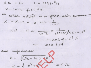
Que-46: A capacitor, a resistor of 5 Ω and an inductor of 50 mH are in series with an AC source marked 100 V, 50 Hz. It is found that voltage is in phase with the current. Calculate the capacitance of the capacitor and impedance of the circuit. (π = 3.14)
Ans-
— : End of V L C R Circuit Numerical Class-12 Nootan ISC Physics Solution Ch-12 Alternating Current . :–
Return to : – Nootan Solutions for ISC Class-12 Physics
Thanks
Please share with your friends