Household Circuits ICSE Class-10 Concise Physics Selina Solutions Chapter-9. We Provide Step by Step Answer of Exercise-9(A), MCQs-9(A), Exercise-9(B), MCQs-9(B) Questions of Exercise-9 Household Circuits ICSE Class-10 . Visit official Website CISCE for detail information about ICSE Board Class-10.
| Board | ICSE |
| Publications | Selina Publication |
| Subject | Physics |
| Class | 10th |
| Chapter-9 | Household Circuits (Exercise 9A) |
| Book Name | Concise |
| Topics | Solution of Exercise-9(A), MCQs-9(A), Exercise-9(B), MCQs-9(B) |
| Academic Session | 2021-2022 |
Household Circuits ICSE Class-10 Concise Physics Selina Solutions Chapter-9
-: Select Exercise :-
Exercise-9(A), MCQs-9(A)
How to Solve Household Circuits ICSE Class-10 Physics
Focus on main circuit, switches, fuses, earthing, safety precautions, three pin plugs, colour coding of wires. Household Circuit diagram, two-way switch, staircase wiring, need for earthing, fuse, 3-pin plug and socket, , neutral and earth points in 3-pin plugs and sockets; safety precautions, colour coding of wires.
Excercise – 9 (A) Household Circuits ICSE Class-10
Page 218
Question 1
At what voltage and frequency is the electric power generated at the power generating station?
Answer 1
The electric power is generated at 11 KV, 50 Hz at the power generating station.
Question 2
(a) At what voltage is the electric power from the generating station transmitted? Give reasons to your answer.
(b) What is the nature of current transmitted from the power station?
Answer 2
(a) Electric power from the generating station is transmitted at 11 kV because voltage higher than this causes insulation difficulties, while the voltage lower than this involves high current and loss of energy in form of heat (I2Rt).
(b) The current transmitted from the power station is alternating in nature.
Question 3
In the transmission of power the voltage of power generated at the generating station is stepped up from 11kV to 132kV before it is transmitted. Why?
Answer 3
The voltage is stepped up from 11kV to 132kV to minimize the loss of energy in the form of heat in the live wires used for transmission.
Question 4
Explain with the aid of a simple diagram, the transmission of electric power from the generating station to your house.
Answer 4
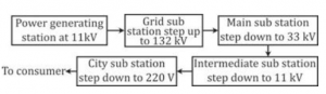
At a power generating station, the electric power is generated at 11 kV. From here, the alternating voltage is transmitted to the grid sub-station and stepped up to 132 kV using a step-up transformer. It is then transmitted to the main sub-station where the voltage is stepped down to 33 kV using a step-down transformer and is then transmitted to the intermediate sub-station. At the intermediate sub-station, the voltage is stepped down to 11 kV using a step-down transformer and is transmitted to the city sub-station, where the voltage is further stepped down to 220 V and is supplied to our houses.
Question 5
At what (i) voltage and (ii) frequency is the a.c. supplied to our houses?
Answer 5
(i) At 220 V of voltage and (ii) 50 Hz of frequency, the a.c. is supplied to our houses.
Question 6
Name the device used to (a) Increase the voltage at the generating station (b) Decrease the voltage at the sub-station for its supply.
Answer 6
(a) Step-up transformer
(b) Step-down transformer
Question 7
(a) Name the three connecting wires used in a household circuit.
(b) Which two wires mentioned in part (a) are at the same potential?
(c) In which of the wire stated in part (a) the switch is connected?
Answer 7
(a) The three connecting wires used in a household circuit are:
(i) Live (or phase) wire (L),
(ii) Neutral wire (N), and
(iii) Earth wire (E).
(b) Among them neutral and earth wires are at the same potential.
(c) The switch is connected in the live wire.
Question 8
What is the pole fuse? Write down its current rating.
Answer 8
Before the electric line is connected to the meter in a house, a fuse of rating (≈50 A) is connected in the live wire at the pole or just before the meter. This fuse is called the pole fuse.
Its current rating is .≈ 50 A
Question 9
State the function of each of the following in a house circuiting:
(a) kWh meter,
(b) main fuse, and
(c) main switch.
Answer 9
(a) After the company fuse, the cable is connected to a kWh meter and from this meter; connections are made to the distribution board through a main fuse and a main switch.
(b) Main fuse is connected in the live wire and in case of high current it gets burnt and cut the connections to save appliances.
(c) Main switch is connected in the live and neutral wires. It is used to cut the connections of the live as well as the neutral wires simultaneously from the main supply.
Question 10
In what unit does the electric meter in a house measure the electrical energy consumed? What is its value in S.I. unit?
Answer 10
The electric meter in a house measures the electrical energy consumed in kWh.
Its value in S.I. unit is .
Question 11
Where is the main fuse connected in a house circuit?
Answer 11
The main fuse in a house circuit is connected on the distribution board, in live wire before the main switch.
Question 12
State one advantage of using the main switch in house wiring.
Answer 12
The main switch is a double pole switch with an iron covering.
The major advantage of using a main switch is that it can break the connection of both, the live and the neutral wire at the same time.
This protects electrical appliances from accidental damage due to electrical faults.
Question 13
Draw a circuit diagram to explain the ring system of house wiring. State two advantages of it.
Answer 13
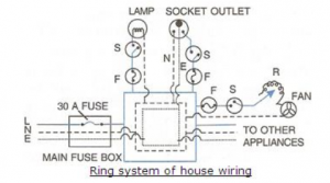
Advantages of ring system over tree system
(i) In a ring system the wiring is cheaper than tree system.
(ii) In ring system the sockets and plugs of same size can be used while in a tree system sockets and plugs are of different size.
(iii) In ring system, each appliance has a separate fuse due to which if there is a fault and the fuse of one appliance burns it does not affect other appliances; while in a tree system when fuse in one distribution line blows, it disconnects all the appliances connected to that distribution circuit.
Page 219
Question 14
Draw a labelled diagram with necessary switch, regulator etc. to connect a bulb/lamp, a plug socket and a fan with the mains.In what arrangement are these appliances connected to the mains: series or parallel?
Answer 14
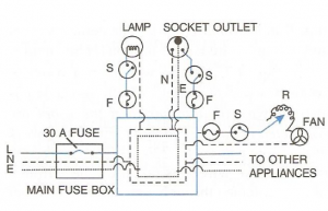
These appliances are connected to the mains in a parallel arrangement.
Question 15
How should the several electric lamps be connected with the main so that the switching on or off in a room has no effect on other lamps?
Answer 15
All the electrical appliances in a building should be connected in parallel at the mains, each with a separate switch and a separate fuse connected in the live wire so that the switching on or off in a room has no effect on other lamps in the same building.
Question 16
Fig.9.12 shows three bulbs A, B and C each of rating 100 W, 220 V connected to the mains of 220 V. Answer the following:
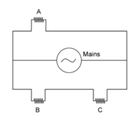
(a) How is the bulb A connected with the mains? At what voltage does it glow?
(b) How are the bulbs B and C connected with the mains? At what voltage does the bulb B glow ?
(c) How is the glow of bulbs A and C affected if bulb B gets fused?
(d) How is the glow of bulbs B and C affected if bulb A gets fused?
Answer 16
(a) Bulb A is connected in a parallel connection with the mains.
It will glow when the voltage applied across the bulb is 220 V.
(b) Bulbs B and C are connected in series with the mains. Because of this series connection with the mains, the voltage at which they glow will be divided by two from the main’s supply voltage. So, bulb B will glow at 110 V.
(c) If bulb B gets fused, bulb C which was connected in series with it will not glow. This will not affect the glow of bulb A, because it is connected parallel with the mains.
(d) If bulb A gets fused, the glow of bulbs B and C will not be affected.
Question 17
Two sets A and B each of four bulbs are glowing in two separate rooms. When one of the bulbs in set A is fused, the other three bulbs also cease to glow. But in set B, when one bulb fuses, the other bulbs continue to glow.
(i) Explain the difference in the two sets,
(ii) Which set of arrangement is preferred in housing circuit and why?
[Hint : in set A, the bulbs are in series; while in set B, the bulbs are in parallel]
Answer 17
In set A, the bulbs are connected in series. Thus, when the fuse of one bulb blows off, the circuit gets broken and current does not flow through the other bulbs also.
In set B, the bulbs are connected in parallel. Thus, each bulb gets connected to its voltage rating (= 220 V) and even when the fuse of one bulb blows off, others remain unaffected and continue to glow.
Chapter 9 : Household Circuits Selina Physics Solutions
MULTIPLE CHOICE TYPE – 9 (A)
Page 219
Question 1
The main fuse is connected in :
(a) Live wire
(b) Neutral wire
(c) Both the live and earth wires
(d) Both earth and the neutral wire.
Answer 1
(a) The main fuse is connected in live wire.
Question 2
The electrical appliances in a house are connected in :
(a) Series
(b) Parallel
(c) Either in series or parallel
(d) Both in series and parallel
Answer 2
(b) Electrical appliances in a house are connected in parallel.
Question 3
The electric meter in a house records the consumption of :
(a) Charge
(b) Current
(c) Energy
(d) Power
Answer 3
(c) Energy
Return to Concise Selina ICSE Physics Class-10
Thanks


1 thought on “Household Circuits ICSE Class-10 Concise Physics Selina Solutions”
Sorry sir, but
The answers of ICSE Physics class 10th Chapter 9. the Household circuits, exercise 9A, 9th question’s answers are wrong.
Please check!