Nootan Solutions Torque on Current-Loop Moving-Coil Galvanometer ISC Physics Class-12 Nageen Prakashan Chapter-8 Solved Numericals. Step by step Solutions of Kumar and Mittal ISC Physics Class-12 Nageen Prakashan Numericsls Questions. Visit official Website CISCE for detail information about ISC Board Class-12 Physics
Nootan Solutions Torque on a Current-Loop Moving-Coil Galvanometer ISC Physics Class-12 Nageen Prakashan Chapter-8, Solved Numericals of Kumar and Mittal
| Class: | 12 |
| Subject: | Physics |
| Chapter 8: | Torque on a Current-Loop Moving-Coil Galvanometer |
| Board | ISC |
| Writer /Publications | Nootan / Nageen Prakashan/Kumar and Mittal |
| Topics | Solved Numericals of page 413,414 |
What is a Moving Coil Galvanometer?
A moving coil galvanometer is an instrument which is used to measure electric currents. It is a sensitive electromagnetic device which can measure low currents even of the order of a few microamperes.
Moving-coil galvanometers are mainly divided into two types:
- Suspended coil galvanometer
- Pivoted-coil or Weston galvanometer
Moving Coil Galvanometer Principle
A current-carrying coil when placed in an external magnetic field experiences magnetic torque. The angle through which the coil is deflected due to the effect of the magnetic torque is proportional to the magnitude of current in the coil.
Moving Coil Galvanometer Construction And Diagram
The moving coil galvanometer is made up of a rectangular coil that has many turns and it is usually made of thinly insulated or fine copper wire that is wounded on a metallic frame. The coil is free to rotate about a fixed axis. A phosphor-bronze strip that is connected to a movable torsion head is used to suspend the coil in a uniform radial magnetic field.
Essential properties of the material used for suspension of the coil are conductivity and a low value of the torsional constant. A cylindrical soft iron core is symmetrically positioned inside the coil to improve the strength of the magnetic field and to make the field radial. The lower part of the coil is attached to a phosphor-bronze spring having a small number of turns. The other end of the spring is connected to binding screws.
The spring is used to produce a counter torque which balances the magnetic torque and hence help in producing a steady angular deflection. A plane mirror which is attached to the suspension wire, along with a lamp and scale arrangement is used to measure the deflection of the coil. Zero-point of the scale is at the centre.
Working of Moving Coil Galvanometer
Let a current I flow through the rectangular coil of n number of turns and a cross-sectional area A. When this coil is placed in a uniform radial magnetic field B, the coil experiences a torque τ.
Let us first consider a single turn ABCD of the rectangular coil having a length l and breadth b. This is suspended in a magnetic field of strength B such that the plane of the coil is parallel to the magnetic field. Since the sides AB and DC are parallel to the direction of the magnetic field, they do not experience any effective force due to the magnetic field. The sides AD and BC being perpendicular to the direction of field experience an effective force F given by F = BIl
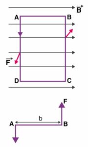
Using Fleming’s left-hand rule we can determine that the forces on AD and BC are in opposite direction to each other. When equal and opposite forces F called couple acts on the coil, it produces a torque. This torque causes the coil to deflect.
We know that torque τ = force x perpendicular distance between the forces
τ = F × b
Substituting the value of F we already know,
Torque τ acting on single-loop ABCD of the coil = BIl × b
Where lx b is the area A of the coil,
Hence the torque acting on n turns of the coil is given by
τ = nIAB
The magnetic torque thus produced causes the coil to rotate, and the phosphor bronze strip twists. In turn, the spring S attached to the coil produces a counter torque or restoring torque kθ which results in a steady angular deflection.
Under equilibrium condition:
kθ = nIAB
Here k is called the torsional constant of the spring (restoring couple per unit twist). The deflection or twist θ is measured as the value indicated on a scale by a pointer which is connected to the suspension wire.
θ= ( nAB / k)I
Therefore θ ∝ I
The quantity nAB / k is a constant for a given galvanometer. Hence it is understood that the deflection that occurs the galvanometer is directly proportional to the current that flows through it.
Solved question: What is the purpose of introducing a cylindrical soft iron core inside the moving coil galvanometer?
Solution: The cylindrical soft iron core placed inside the galvanometer increases the magnetic field strength, thereby improving the sensitivity of the instrument. It also makes the magnetic field radial so that the angle between the plane of the coil and the magnetic lines of force remains zero at all times during the rotation of the coil.
Sensitivity Of Moving Coil Galvanometer
The general definition of the sensitivity experienced by a moving coil galvanometer is given as the ratio of change in deflection of the galvanometer to the change in current in the coil.
S = dθ/dI
The sensitivity of a galvanometer is higher if the instrument shows larger deflection for a small value of current. Sensitivity is of two types, namely current sensitivity and voltage sensitivity.
- Current Sensitivity
The deflection θ per unit current I is known as current sensitivity θ/I
θ/I = nAB/k
- Voltage Sensitivity
The deflection θ per unit voltage is known as Voltage sensitivity θ/V. Dividing both sides by V in the equation θ= (nAB / k)I;
θ/V= (nAB /V k)I = (nAB / k)(I/V) = (nAB /k)(1/R)
R stands for the effective resistance in the circuit.
It is worth noting that voltage sensitivity = Current sensitivity/ Resistance of the coil. Therefore under the condition that R remains constant; voltage sensitivity ∝ Current sensitivity.
Figure of Merit of a Galvanometer
It is the ratio of the full-scale deflection current and the number of graduations on the scale of the instrument. It also the reciprocal of the current sensitivity of a galvanometer.
Factors Affecting Sensitivity Of A Galvanometer
a) Number of turns in the coil
b) Area of the coil
c) Magnetic field strength B
d) The magnitude of couple per unit twist k/nAB
Solved Question: Increase in current sensitivity results in an increase in voltage sensitivity of a moving coil galvanometer. Yes or no? Justify your answer.
Solution: No. An increase in current sensitivity of a moving coil galvanometer may not necessarily result in an increase in voltage sensitivity. As the number of turns(length of the coil) is increased to increase the current sensitivity of the device, the resistance of the coil changes. This is because the resistance of the coil is dependent on factors like the length and area of the coil.
As we know that voltage sensitivity θ/V = (nAB /k)(1/R); the overall value of voltage sensitivity remains unchanged.
Solved Numericals of Torque on a Current-Loop Moving-Coil Galvanometer Nootan Solutions, Nageen Prakashan Kumar and Mittal
Page- 413,414
—: End of Nootan Solutions Torque on a Current-Loop Moving-Coil Galvanometer of Numericals :–
Return to – Nootan Solutions for ISC Physics Class-12 Nageen Prakashan
Thanks